How Do You Test and Troubleshoot Powered Cable Systems?
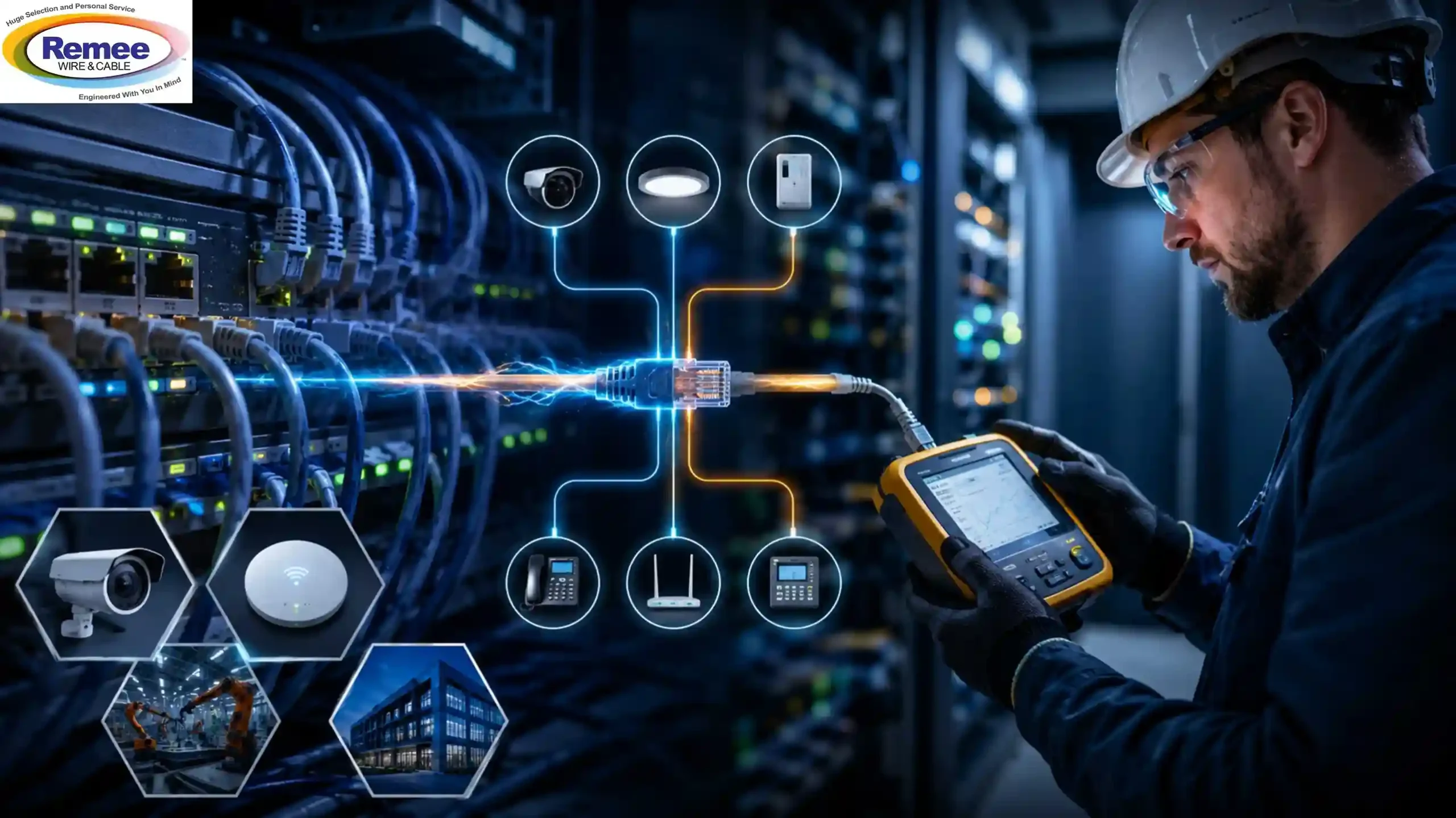
Powered networks now do far more than simply carry data. Modern Powered Cable Systems often deliver both power and data connectivity through the same cable, whether supporting PoE cameras, wireless access points, industrial controls, or Class 4 fault-managed systems.
That convenience also introduces new troubleshooting challenges. A cable may pass basic certification testing yet still create intermittent power problems later under real operating conditions. This is why proper testing procedures for PoE systems and Class 4 installations matter just as much as the cable itself.
This guide explores practical testing methods, common field issues, and what installers should verify before a Powered Cable System goes live.
Why Powered Cable Systems Create New Challenges
Most network failures are not dramatic. There are usually no sparks or total shutdowns. Instead, problems often begin with small inconsistencies:
● A camera randomly rebooting
● A wireless access point drops during peak usage
● Devices are becoming unstable weeks after installation
This is what makes troubleshooting frustrating.
Traditional cabling focused primarily on signal integrity. Powered Cable Systems introduce additional variables because the infrastructure carries both data and an electrical load simultaneously,
such as:
● Heat buildup
● Resistance
● Poor terminations
● Voltage loss
● Cable distance
It becomes far more important than many teams expect during planning.
This is especially true in larger PoE deployments and Class 4 fault-managed systems where power demand, conductor size, and cable distance directly affect long-term reliability.
Large powered networks leave very little room for infrastructure mistakes. Talk with our team.
Why Testing Matters More in Powered Cable Systems
A structured cabling link may appear fully functional during standard certification testing, but may struggle once powered devices begin operating under load.
As power requirements increase, even small installation issues become easier to detect. Minor resistance in connectors, inconsistent pair termination, excessive cable length, or poor pathway conditions can eventually impact stability.
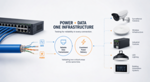
In Powered Cable Systems, installers are validating two critical areas at the same time:
● Reliable data transmission
● Consistent power delivery
The second area is often overlooked early in deployment.
This becomes increasingly important in high-power PoE environments supporting:
● Surveillance cameras
● LED lighting
● Wireless infrastructure
● Industrial controls
● Building automation systems
Continuity Testing Still Solves Many Problems
Continuity testing may seem basic, but it continues to identify more installation problems than many teams expect, especially after cable pulling.
Sharp bends, tight conduit runs, excessive pulling tension, or rushed terminations can damage conductors long before the network becomes operational.
Installers typically use continuity testing to verify:
- Proper conductor termination
- Pair integrity
- Open circuits
- Shorts between conductors
- Miswired connections
Sometimes, the entire issue comes down to a single poorly terminated connector hidden within an otherwise clean installation.
That happens more often than most installers admit.
Voltage Drop Testing Becomes Critical Under Load
A cable may pass certification and still fail once powered devices begin drawing current. That is where voltage drop testing becomes essential.
As cable length increases, conductor resistance creates power loss along the run. If the voltage reaching the endpoint falls below operating requirements, powered devices can become unstable even when the data side of the link appears normal.
Common symptoms include:
- Random device reboots
- Intermittent disconnects
- Cameras failing during nighttime IR activation
- Wireless access points are losing stability during peak traffic
- Inconsistent startup behaviour
These problems become more common in larger PoE deployments and long-distance Powered Cable Systems.
Seeing unstable PoE performance under load? Ask an Expert
Remee’s Activate™ Powered Cable Solutions are designed for environments where both power and data stability are critical over long distances. Their PowerPipe™ solutions help address heat and distance limitations commonly found in traditional cabling systems.
Common PoE Problems Installers Encounter
Its failures are rarely caused by a single major issue. More often, several smaller problems combine to create unpredictable behaviour over time.
Typical -related issues include:
- Speed mismatches
- Duplex negotiation problems
- Excessive cable heat buildup
- Poor shielding in high-interference areas
- Improper connector termination
- Power budget overloads on switches
- Cable runs exceeding recommended distances
Higher-power deployments introduce additional thermal concerns because bundled powered cables generate more internal heat. Over time, this temperature increase can affect long-term performance if the cable is not designed specifically for Powered Cable Systems.
Testing Procedures for PoE Systems
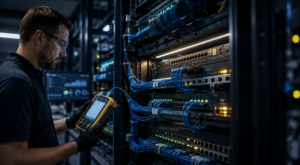
Good testing procedures for PoE systems go beyond basic cable certification.
Installers should test how the link performs under actual operating conditions rather than ideal laboratory environments.
Effective testing procedures for PoE systems generally include:
- Cable certification testing
- Continuity testing
- Voltage drop testing
- Load simulation testing
- PoE power negotiation verification
- Thermal inspection in bundled pathways
- Shielding and grounding validation when required
Experienced installers understand that a system operating perfectly during low-load commissioning may behave very differently once the full device load activates.
This is especially true in dense enterprise and industrial deployments.
Testing Procedures for Class 4 Systems
Class 4 fault-managed power systems introduce another level of complexity because they operate differently from traditional infrastructure.
These systems deliver significantly higher power levels across longer distances while continuously monitoring line conditions for safety.
Installers are not only validating connectivity but also verifying how the system behaves during fault conditions.
Testing procedures for Class 4 systems commonly include:
- Line integrity verification
- Fault detection validation
- Load balancing checks
- Grounding inspection
- Power interruption response testing
- Environmental exposure evaluation for outdoor installations
Unlike smaller PoE systems, Class 4 infrastructure often supports large-scale environments where downtime can become extremely costly.
As a result, the margin for installation error becomes much smaller.
Why Proper Cable Selection Minimizes Troubleshooting Later On
Many troubleshooting calls can be traced back to cable selection decisions made early in the project. Sometimes the problem is not installation quality at all; it is simply the wrong cable for the application environment.
Powered Cable Systems generate heat differently than traditional structured cabling. Higher wattage loads, bundled pathways, outdoor exposure, and longer cable distances place additional stress on the infrastructure.
Planning a high-power PoE or Class 4 deployment? Requisition for detailed information.
This is why installers pay closer attention to:
- Conductor size
- Heat performance
- Shielding requirements
- Environmental ratings
- Power classification compatibility
- Indoor versus outdoor deployment conditions
Activate™ by Remee Powered Cable Solutions include:
- PoE-rated category cables
- Class 4 PowerPipe™ Copper Distribution Cables
- PowerPipe™ Hybrid Fiber/copper Constructions
These products are designed for both indoor and outdoor powered network environments.
Testing Powered Cable Systems now involves much more than proving basic network connectivity. Installers must validate long-term power stability under real operating conditions.
Continuity testing, voltage drop testing, thermal inspection, and proper testing procedures for PoE systems all help reduce failures that may not appear during initial certification. The same applies to testing procedures for Class 4 systems, where both safety and power delivery are critical to overall system performance.
Once powered infrastructure begins supporting lighting, automation, wireless access, surveillance, or industrial controls, expectations for reliability change quickly.
In many cases, the cable problems teams face later were already present during installation; They simply had not appeared yet.
Frequently Asked Questions
Q1: What are Powered Cable Systems used for?
A: Powered Cable Systems are commonly used in applications that require both power and data transmission over the same cable infrastructure, including PoE cameras, wireless access points, LED lighting, industrial controls, and Class 4 fault-managed systems.
Q2: Why is voltage drop testing important in PoE installations?
A: Voltage drop testing helps ensure powered devices receive sufficient voltage throughout the cable run during PoE installation. Excessive voltage loss can cause device instability, random reboots, and inconsistent performance.
Q3: What most often causes PoE failures?
A: Common causes include poor terminations, excessive cable lengths, heat buildup in bundled pathways, switch power budget overloads, speed mismatches, and improper shielding.
Q4: What is continuity testing used for in powered cabling?
A: Continuity testing verifies conductor integrity and helps identify open circuits, shorts, pair miswires, and damaged conductors before the network becomes operational.
Q5: How are Class 4 systems different from traditional PoE?
A: Class 4 systems deliver higher power levels over longer distances while continuously monitoring line conditions for safety and fault management, which is why proper testing procedures for Class 4 systems are essential.