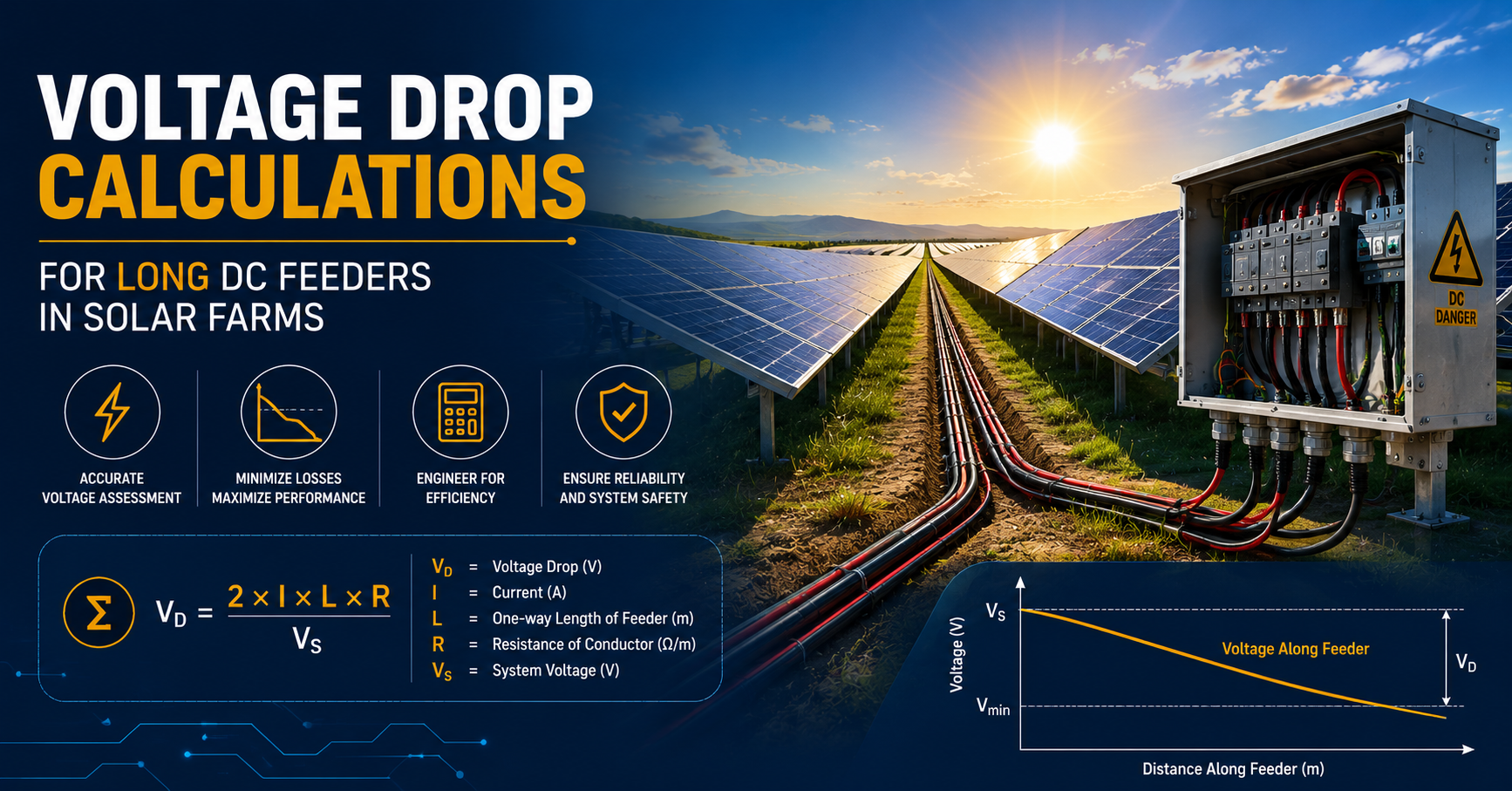
Voltage Drop Calculations for Long DC Feeders in Solar Farms
As solar farms continue to expand, maintaining efficient power transmission over long cable runs remains a major design challenge. One of the biggest concerns is voltage drop in DC feeders, which can reduce system efficiency, increase energy losses, and affect the overall performance of photovoltaic (PV) installations.
Proper voltage drop calculations help engineers determine the correct conductor size, optimize cable routing, and ensure compliance with electrical standards. By combining accurate calculations with the right PV wire and feeder cable selection, designers can improve energy output while minimizing installation and operating costs.
In this guide, we’ll explain how to calculate voltage drop for long DC feeder runs, discuss conductor sizing considerations, and explore practical strategies for reducing power losses in utility-scale solar farms.
What Are DC Feeders?
DC feeders are the cables that carry direct current generated by photovoltaic modules from combiner boxes to inverters or other power conversion equipment. They play a critical role in transporting energy across a solar farm while minimizing electrical losses.
Unlike short rooftop installations, utility-scale solar projects often require feeder runs that extend hundreds or even thousands of feet. As cable length increases, so does electrical resistance, making voltage drop a key design consideration.
Common applications include:
- Utility-scale solar farms
- Commercial photovoltaic systems
- Ground-mounted solar arrays
- Community solar projects
- Battery energy storage integrations
Selecting properly sized DC feeders helps maximize energy production while maintaining system efficiency.
Explore high-performance DC feeders designed for reliable, efficient solar power transmission.
Why Voltage Drop Matters
Voltage drop is the reduction in electrical voltage as current travels through a conductor.
Excessive voltage drop can result in:
- Lower energy delivered to inverters
- Increased power losses
- Reduced system efficiency
- Higher operating temperatures
- Lower return on investment
- Difficulty meeting design specifications
Because solar systems generate electricity continuously throughout the day, even small efficiency losses can add up to significant energy losses over the life of the project.
Select DC feeders built for reliable power delivery.
Factors That Affect Voltage Drop
Several variables influence voltage drop in DC feeders.
-
Cable Length
Longer cable runs create greater resistance, increasing voltage loss.
-
Current
Higher current levels result in greater voltage drop.
-
Conductor Material
Copper offers lower resistance than aluminum, while aluminum provides weight and cost advantages when properly sized.
-
Conductor Size
Larger conductors reduce electrical resistance and minimize voltage drop.
-
Operating Temperature
Higher temperatures increase conductor resistance, slightly increasing voltage drop.
Voltage Drop Formula for DC Feeders
The standard voltage drop formula for direct current circuits is:
Voltage Drop (V) = (2 × Length × Current × Resistance) ÷ 1000
Where:
- Length = One-way cable length
- Current = Circuit current (A)
- Resistance = Cable resistance (Ω/km or Ω/1000 ft)
- Factor of 2 accounts for the outgoing and return conductors
The percentage voltage drop is calculated as:
Voltage Drop (%) = (Voltage Drop ÷ System Voltage) × 100
Many solar designers aim to keep total DC voltage drop between 1% and 3%, depending on project requirements and applicable electrical codes.
Example Voltage Drop Calculation
Consider a solar array with:
- System Voltage: 1,500 VDC
- Current: 180 A
- One-way cable length: 250 meters
- Aluminum feeder resistance: 0.206 Ω/km
Calculation:
Voltage Drop
= (2 × 250 × 180 × 0.206) ÷ 1000
= 18.54 V
Voltage Drop Percentage
= (18.54 ÷ 1500) × 100
= 1.24%
This result falls within commonly accepted design limits for utility-scale photovoltaic installations.
Conductor Sizing Considerations
Selecting the proper conductor size is essential for minimizing voltage drop while controlling project costs.
Engineers should evaluate:
- Maximum operating current
- Total cable length
- Ambient temperature
- Installation method
- Voltage drop targets
- Future expansion requirements
Oversized conductors reduce energy losses but increase material costs. Proper sizing balances efficiency and budget.
Typical Conductor Sizing Guidelines
The table below illustrates general design trends for DC feeders.
| Feeder Length | Typical Design Approach |
| Under 100 m | Standard conductor sizes often meet voltage drop requirements |
| 100–300 m | Larger conductor sizes may be required |
| Over 300 m | Detailed voltage drop analysis is recommended |
| Utility-scale arrays | Aluminum feeders often provide an economical solution |
Actual conductor selection should always be based on project-specific engineering calculations and applicable electrical standards.
Choosing the Right PV Wire
While DC feeders transport power over longer distances, PV wire connects solar modules and string circuits within the array.
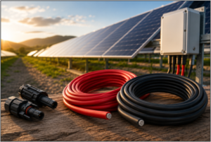
High-quality PV wire offers:
- UV resistance
- Moisture resistance
- High-temperature performance
- Flexibility for installation
- Long outdoor service life
- Compliance with renewable energy standards
Using certified PV wire alongside properly sized feeder cables ensures reliable performance throughout the entire DC collection system.
Strategies to Reduce Voltage Drop
Several design practices help improve efficiency across long feeder runs.
Optimize Combiner Box Placement
Positioning combiner boxes closer to solar arrays reduces feeder length and minimizes voltage losses.
Increase System Voltage
Higher-voltage systems carry the same power with lower current, reducing voltage drop and allowing for smaller conductors.
Use Larger Conductors
Increasing conductor cross-sectional area lowers resistance and improves efficiency.
Minimize Cable Routing
Shorter cable paths reduce resistance and installation costs.
Select Low-Resistance Conductors
High-quality aluminum or copper conductors with optimized electrical characteristics improve system performance.
Why Aluminum DC Feeders Are Growing in Popularity
Many utility-scale solar developers are selecting aluminum DC feeders because they provide an effective balance of performance and cost.
Benefits include:
- Lower material costs
- Reduced cable weight
- Easier transportation and installation
- Excellent long-distance performance
- Suitable for large renewable energy projects
When properly engineered and installed, aluminum feeder cables deliver reliable electrical performance while helping reduce overall project costs.
Applications in Utility-Scale Solar Farms
Properly designed DC feeders support numerous renewable energy projects, including:
- Utility-scale solar farms
- Community solar installations
- Floating solar arrays
- Industrial solar facilities
- Battery energy storage systems
- Renewable energy microgrids
Reliable feeder systems are essential for maximizing energy production and ensuring long-term operational efficiency.
Improve Solar Farm Efficiency with the Right Cable Selection
Accurate voltage drop calculations are a critical part of designing efficient solar farms. Properly sizing DC feeders, selecting durable PV wire, and optimizing cable routing help reduce electrical losses, improve system performance, and maximize energy production over the life of the installation.
Design strategies such as larger conductors, optimized combiner box placement, and higher system voltages can further minimize voltage drop while lowering long-term operating costs.
For renewable energy projects requiring dependable performance, Remee offers high-quality aluminum feeder cables and PV wire solutions engineered to meet the demands of modern solar farms. Their renewable energy cable portfolio is designed to support safe, efficient, and reliable power transmission across utility-scale photovoltaic installations.